Zoeller Well Pump Control Box Wiring Diagram
Https Www Manualshelf Com Manual Zoeller 1451 0007 How To Guide English Spanish Html

Zoeller Steel Control Box In The Water Pump Accessories Department At Lowes Com

Zoeller 10 2338 Control Box For 3 Wire Potable Water Turbine Pump Series 452 1 Hp

Zoeller 842 0008 Model G842 Shark Series Grinder Pump 2 Hp 460 Volts 3 Phase 1 1 4 Npt Discharge 32 Gpm Max 125 Ft Max Head 20 Ft Cord Manual
Zoeller Potable Water Turbine Pumps Buyers Guide Review

Pin On Hydraulics Pneumatics And Pumps
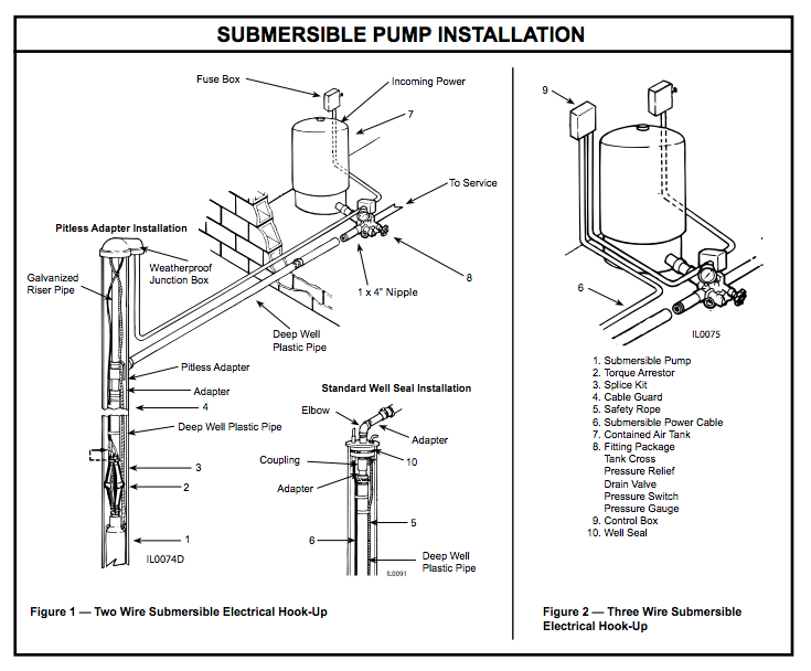
The rugged pump housing features a 1 1 4 discharge and safety rope eyelet for lowering the pump into the well.
Zoeller well pump control box wiring diagram.

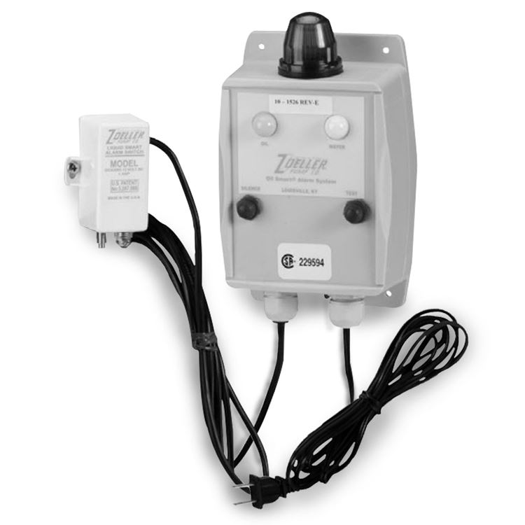
Zoeller 10 1494 Manual Reset Indoor High Water Alarm 115 Vac Plumbing Planet High Water Alarm Vac
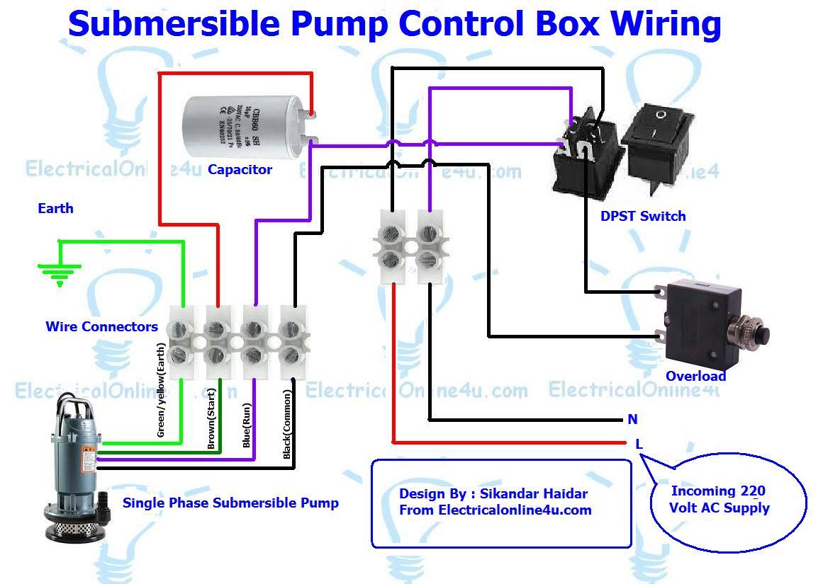
Diagram Zoeller Submersible Pump Wiring Diagram Full Version Hd Quality Wiring Diagram Free0g K Danse Fr

Zoeller 120 Drainage Pump System With Polypropylene Basin Lid
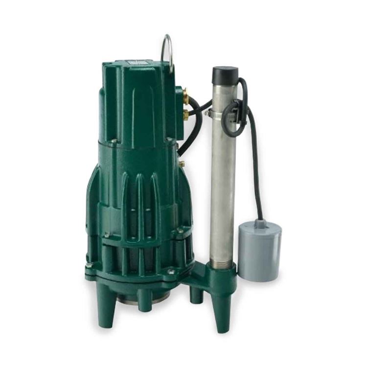
Zoeller Zoeller 818 0007 Model Wd818 Shark Single Directional Grinder Pump 1 0 Hp 230v 1ph 20 Cord Automatic Zlr818 0007
Source : pinterest.com
